Close


Download
1. INTRODUCTION TO THE TRANSMISSIONS
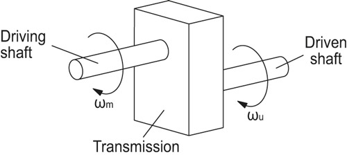
A mechanical transmission is constituted by the complex of the elements required to transmit power in a mechanical system, thus transferring energy from an engine to a user for a certain period of time:

The transfer of this power from the engine to the transmission takes place generally via the driving shaft. A user shaft (also called driven shaft) allows instead the transfer of this power from the transmission to the user.
The power that reaches the user can never be equal to the one coming out of the engine. In fact, during transmission, part of this power will be dissipated by friction or heat. To evaluate how much power is actually used compared to the one generated, then an efficiency value (η) is used:
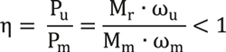
where:
- Driving Power (Pm)= Useful Power (Pu) + Dissipated Power (Pd)
- Mm and Mr are, respectively, the driving torque and the resistant torque.
- ωm and ωu are, respectively, the angular speed of the driving shaft and that of the user shaft.
The driving power is generally expressed as:

Where nm is the number of rounds of the driving shaft expressed in revolutions per minute (rpm) and 9.55 is instead the conversion factor for transforming radians per second in rpm.
The characteristic parameter of the transmission is the transmission ratio (τ), the ratio between the angular speed of the driving shaft and that of the driven shaft:
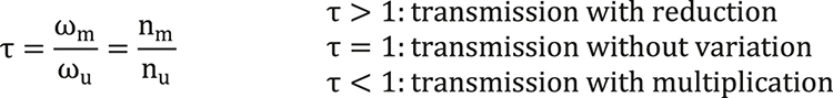
-
Generals
-
1. Plastic materials
- 1.1 Mechanical strength
- 1.2 Thermal resistance
- 1.3 Strength and surface hardness
- 1.4 Resistance to chemical agents
- 1.5 Resistance to atmospheric agents and uv rays
- 1.6 Flame resistance
- 1.7 Electrical properties
- 1.8 Surface finish and cleanability
- 1.9 Compliance with international standards
- 1.10 Competence of Elesa+Ganter technical department
- 2. Metal materials
- 3. Other materials
- 4. Machining tolerances
- 5. Fixed handles
- 6. Assembly measures
- 7. Special executions
- 8. Colours
- 9. Test values
-
10. Technical tables
- 10.1 Conversion tables
- 10.2 DIN 79 Square holes and shafts
- 10.3 DIN 6885 Keyways
- 10.4 GN 110 and GN 110.1 Transversal holes
- 10.5 DIN 13 ISO Metric threads
- 10.6 DIN 228 Cylindrical GAS-BSP threads
- 10.7 DIN EN ISO 898-1 | DIN EN 20898-2 Strenght values
- 10.8 DIN ISO 286 ISO-Fundamental tolerances
- 10.9 IP Protection Classification
- 10.10.1 PFB | PRB Thread locking with jamming action Polyamide patch coating/ Polyamide complete coating
- 10.10.2 MVK Thread locking gluing Micro encapsulation precote 80 (red)
- 10.11 Stainless Steel characteristics
- 10.12 Surface treatments
- 10.13 Carbon steel, zinc alloys, aluminium, brass characteristics
- 10.14.1 Duroplast, elastomer, technopolymer and rubber characteristics
- 10.14.2 Duroplast, elastomer, technopolymer and rubber characteristics
- 10.14.3 Duroplast, elastomer, technopolymer and rubber characteristics
- 10.15 Load ratings U-Handles
- 10.16 Load ratings metal hinges
- 10.17 Strength of indexing plungers
- 10.18 Assembly sets GN 965 and GN 968
- 11. Vibration-damping elements
-
1. Plastic materials
- Hygienic design
- Operating Elements
- Clamping knobs
- Control elements
- Rotary controls
- Indexing elements
- Joints
- Transmission elements
- Levelling elements
- Hinges
- Latches
- Toggle, power and hook clamps
- Accessories for hydraulic systems
- Tube clamp connectors
- Castors and wheels
- Magnets
- Conveyor components
- Linear slides
- Vibration mounts
- Vacuum components
- Elastomer springs